ZYCO
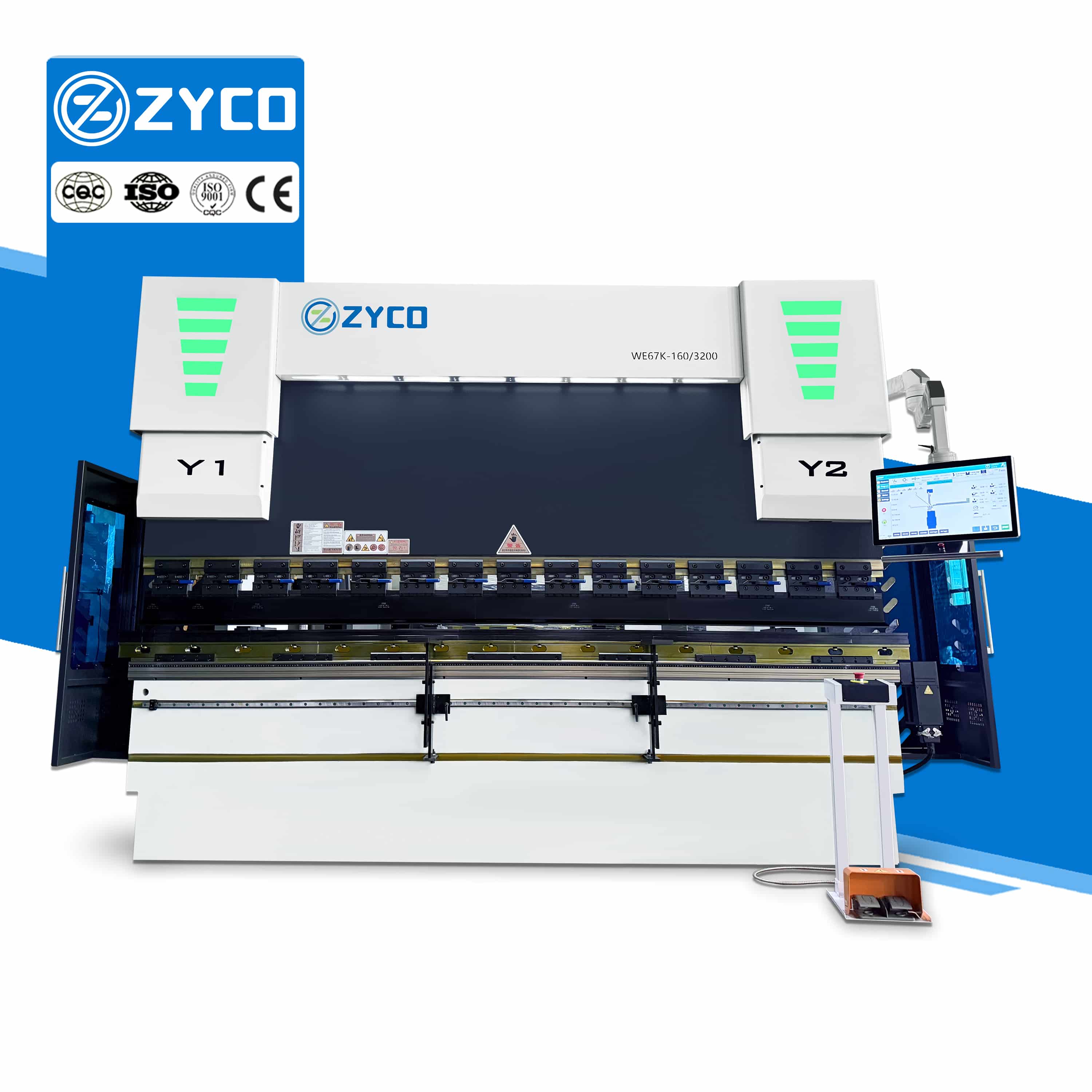
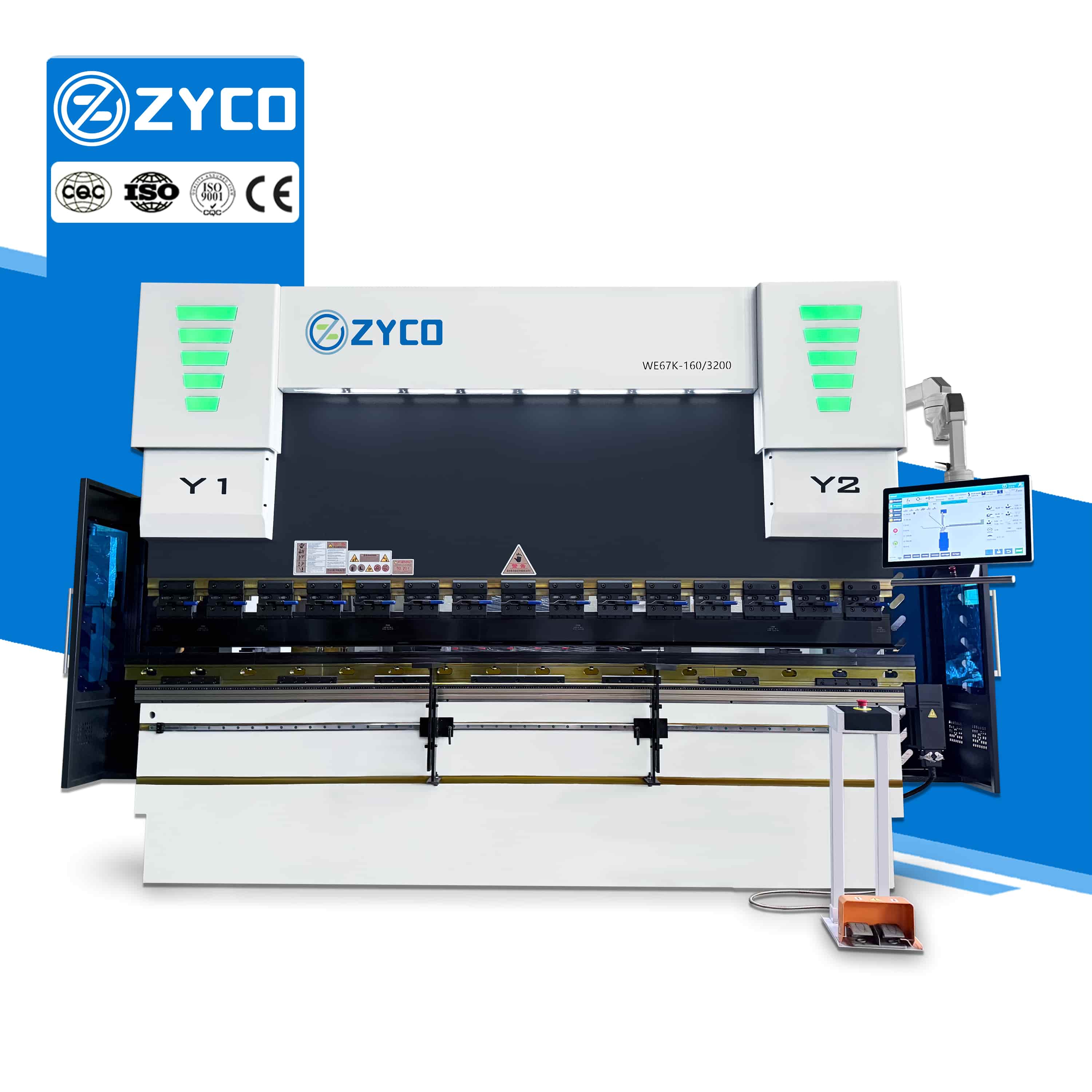
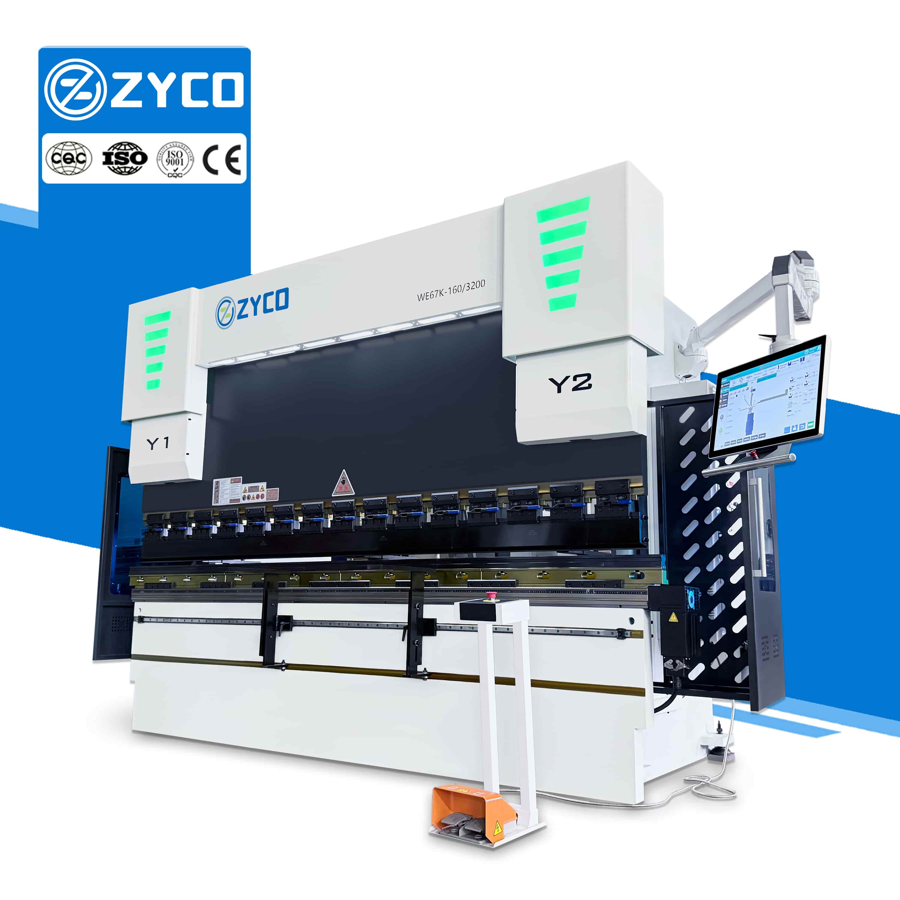
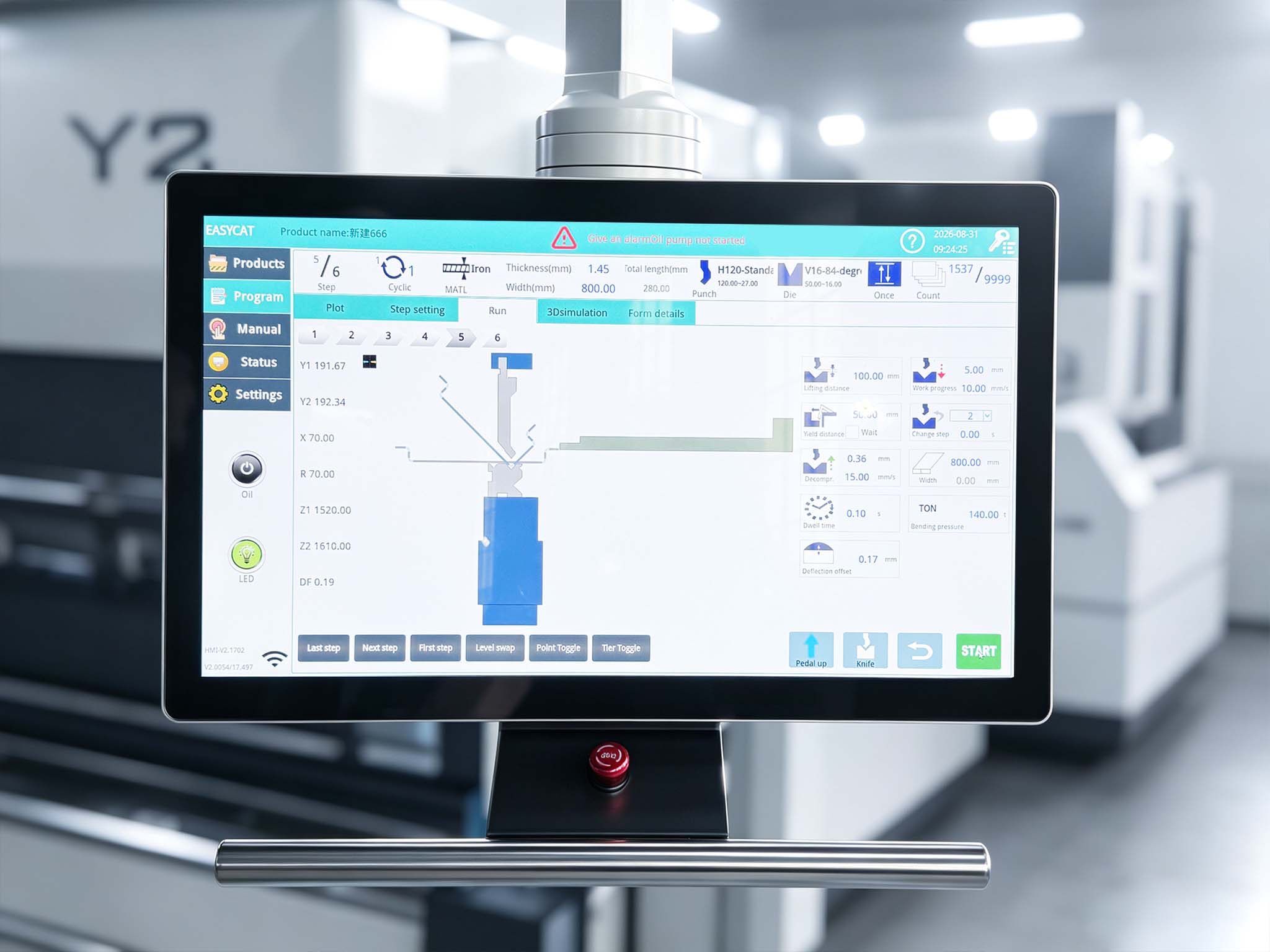
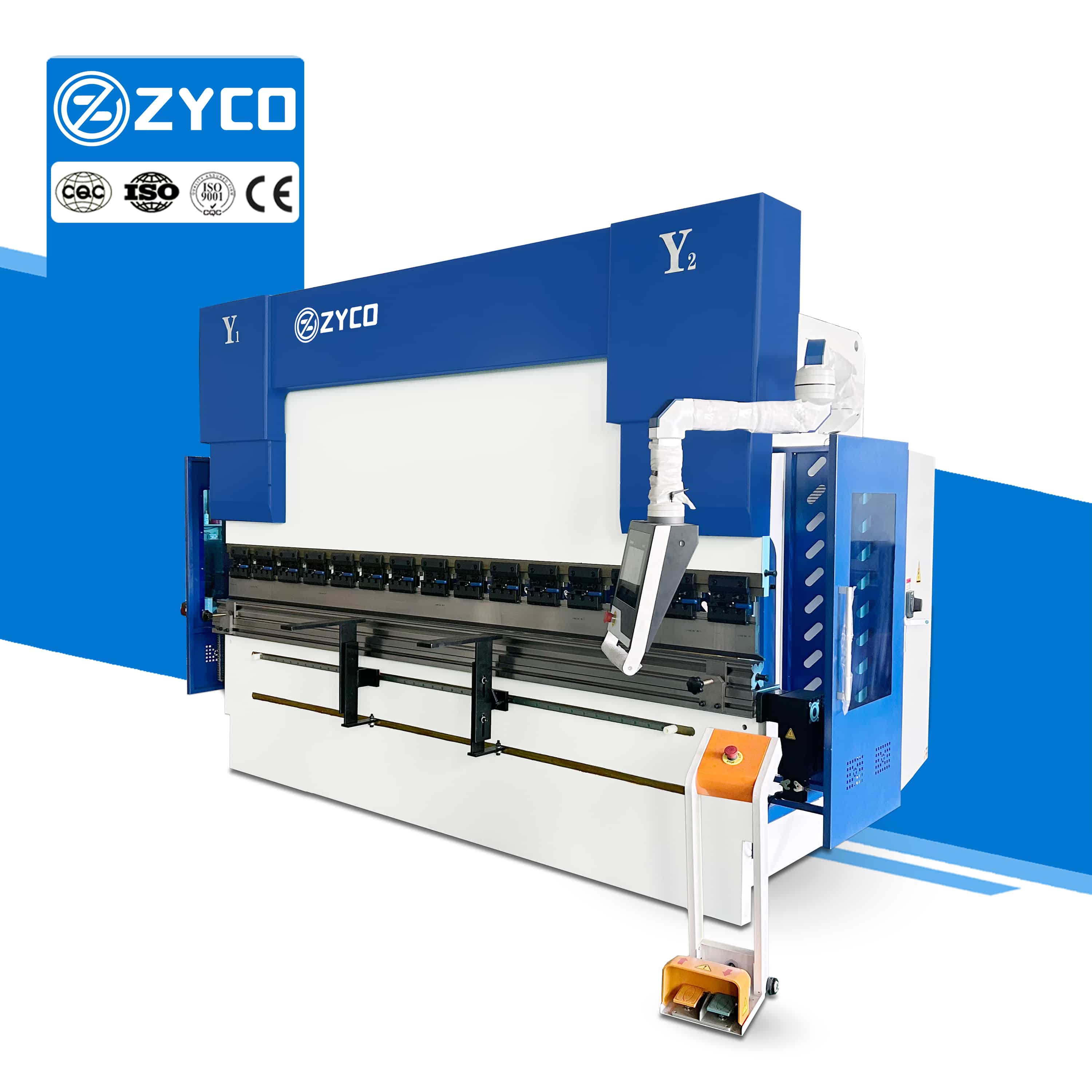
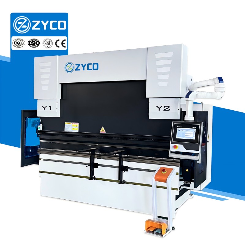
1. The new generation E-Touch electro-hydraulic control system is equipped with a clear and easy-to-understand touch screen operation panel. Large-sized function buttons combined with graphical icon design make programming operations easier and more efficient.
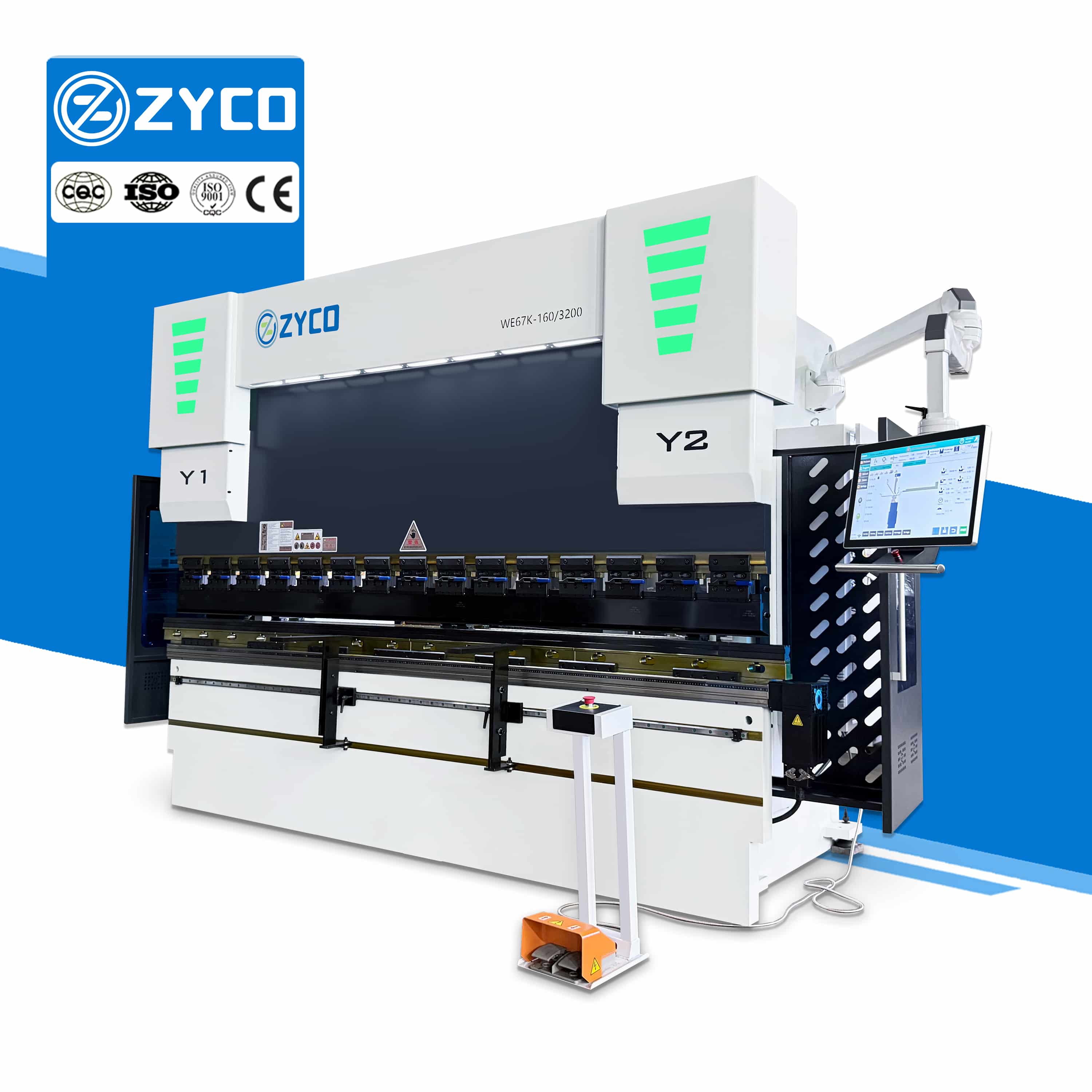
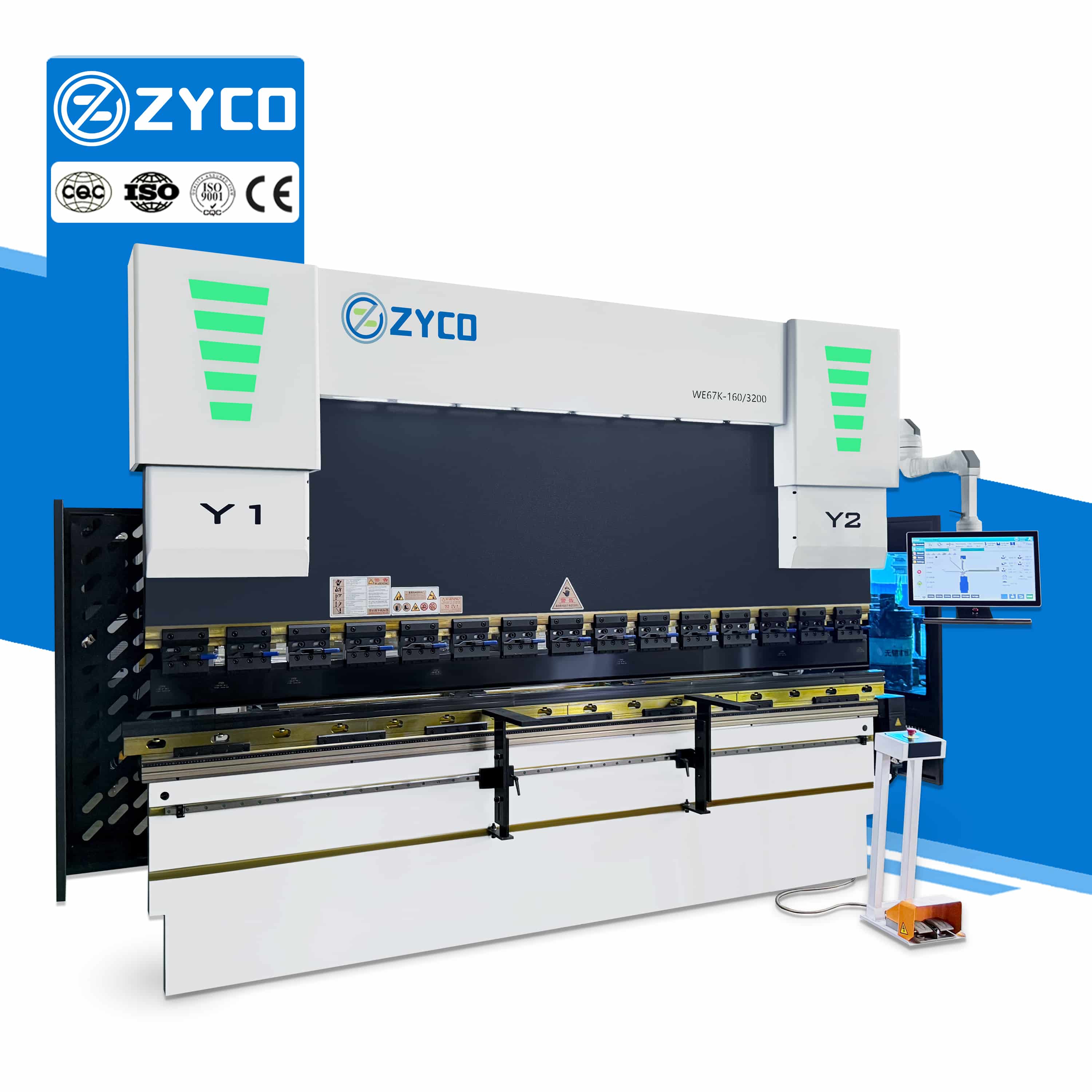
2. Standard configuration supports 6+1 axis linkage control, multi-axis collaborative linkage, and more flexible positioning.
3. The system has a built-in intelligent monitoring and maintenance module, which can provide real-time feedback on the operating status of the equipment, helping operators quickly troubleshoot faults and complete maintenance, thereby improving the stability of equipment operation.
Control system
- The user interface features an intuitive, icon-based layout that significantly simplifies programming for multi-stage bending while effectively reducing production setup time.
- It utilizes a 21.5-inch, high-sensitivity, full-color touchscreen manufactured in Taiwan, supporting multi-touch and swipe gestures with a clear, crisp display.
- The intelligent programming system automatically calculates the optimal bending sequence and performs interference checks, while also allowing for process simulation prior to actual production.
View More +
Electrical cabinet
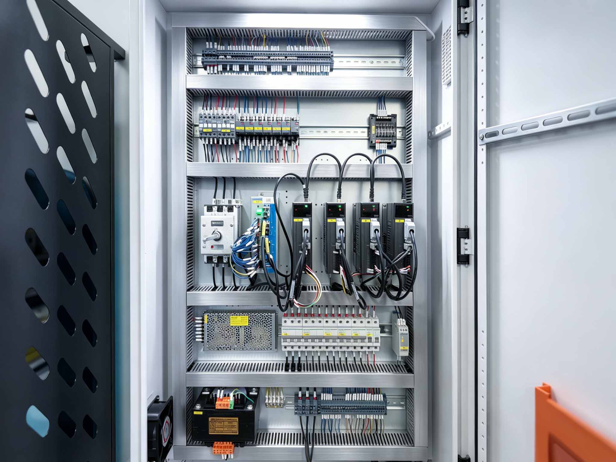
- The electrical cabinet is designed with a clear and well-organized layout, making the internal components easy to inspect and maintain.
- With dedicated control for the 6+1 axis system, the electrical cabinet supports coordinated machine operation and stable positioning performance.
- Power and control wiring are arranged systematically to help reduce electrical interference and make troubleshooting more efficient.
View More +
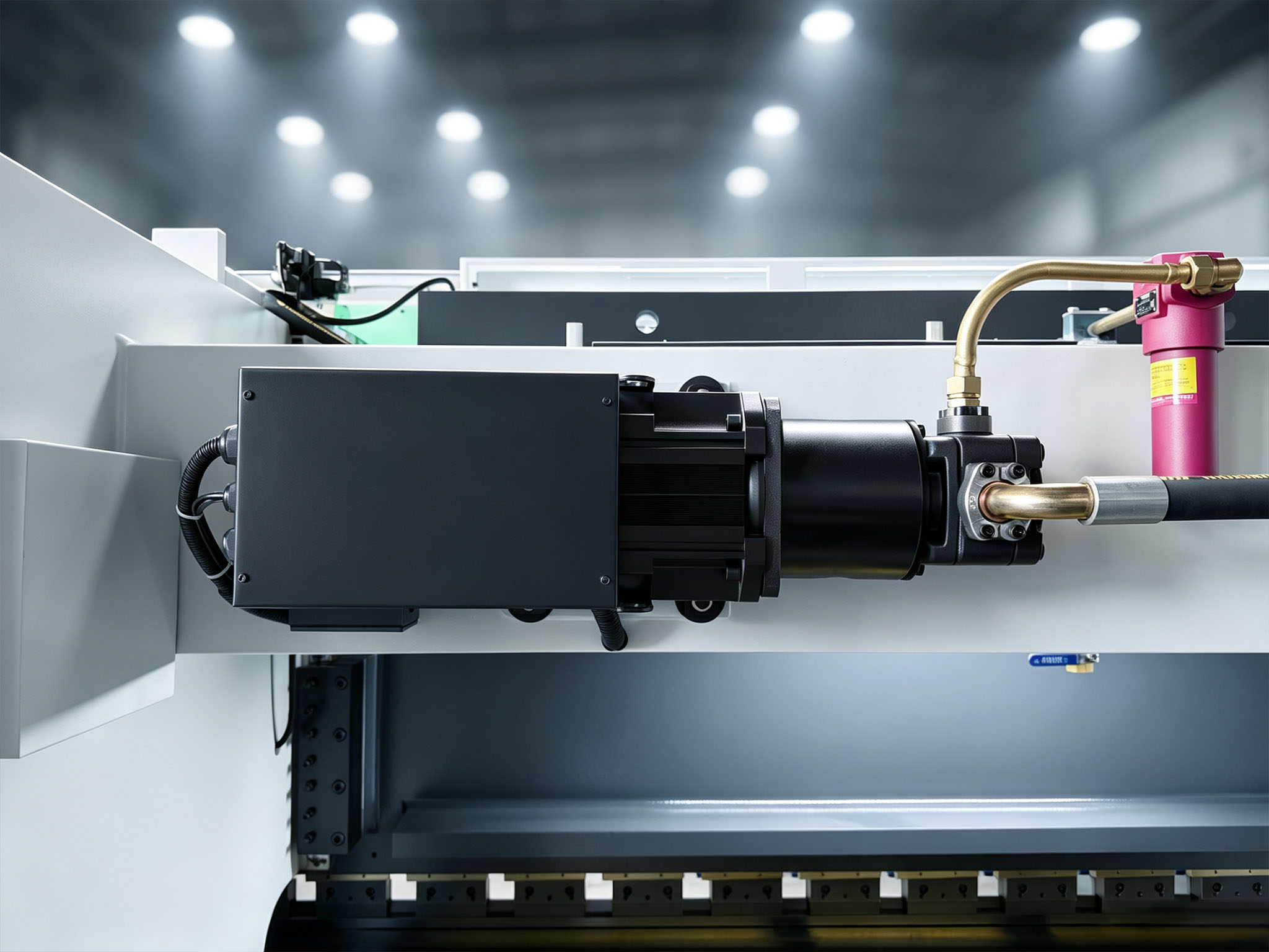
Servo Motor
- The motor provides efficient and stable power for the hydraulic system, supporting consistent machine operation during continuous bending.
- A reliable drive system helps maintain stable machine performance throughout the bending process, particularly during demanding operations.
- An efficient motor and hydraulic system help optimize energy consumption while maintaining the required bending performance.
View More +
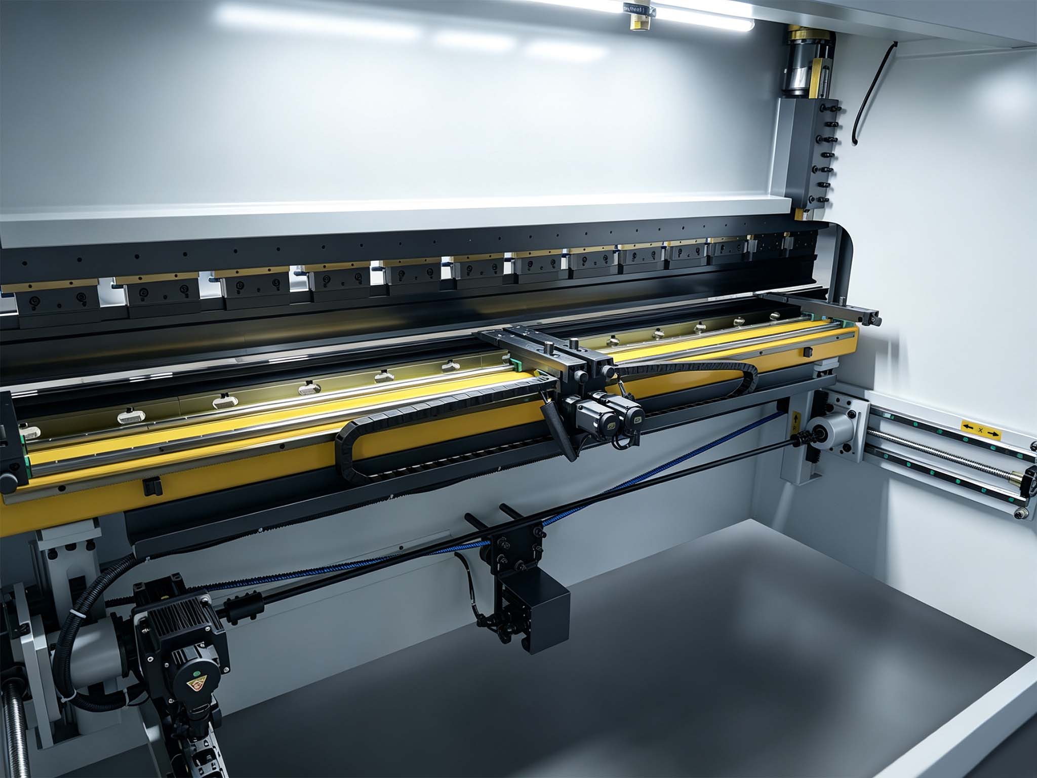
Back gauge
- The drive system utilizes imported high-precision ball screws and linear guides, replacing traditional drive mechanisms to ensure the long-term, stable operation of the slide.
- The machine body structure undergoes high-temperature tempering and aging treatments to effectively relieve machining stresses, thereby preventing accuracy degradation caused by deformation during long-term use.
View More +
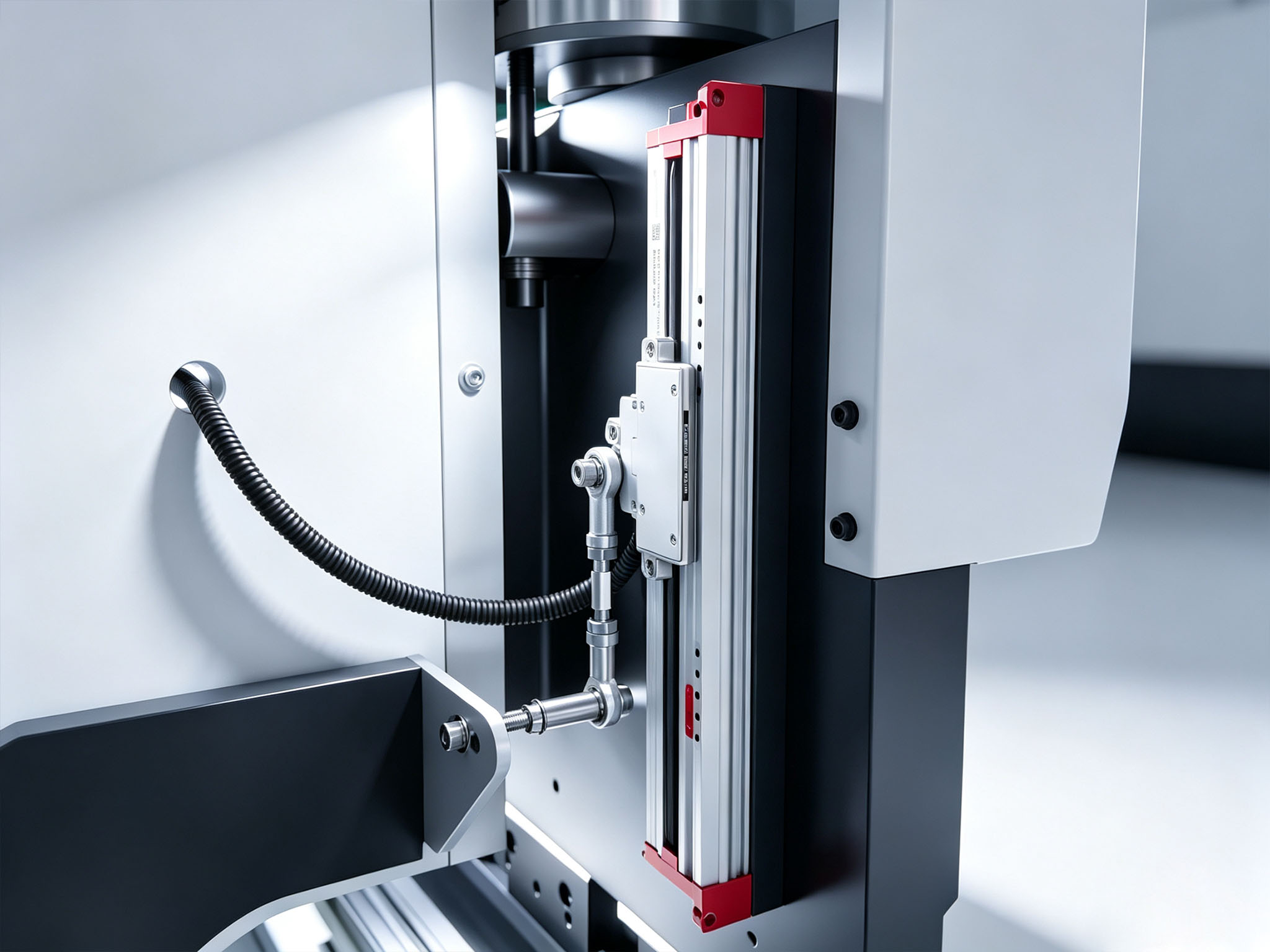
Scale
- The linear scale provides real-time position feedback of the ram, helping the control system accurately monitor its movement.
- By continuously detecting the ram position, the system can make precise corrections during operation, supporting consistent bending angles.
- A properly integrated linear scale system provides continuous feedback throughout machine operation, helping maintain positioning accuracy over repeated cycles.
View More +
Internal Structure Display
For more detailed specifications, please don't hesitate to contact us.
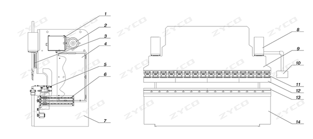
Hydraulic bending machine structure diagram
1.Oil tank 2.Main motor 3.Limit swich 4.Electerical box 5.Stopping finger
6.Back gauge 7.Wall panel 8.Hydraulic oil cylinder 9.Slider 10.CNC system
11.Quick Clamping 12.Upper mold 13.Lower mold 14.Workbench support plate
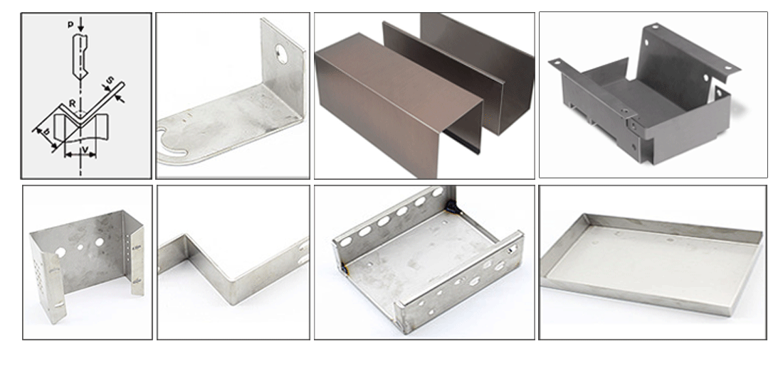
Processing Workpiece Drawing
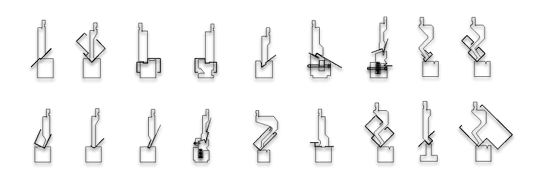

Sample display
|
This page doesn't support show parameter one by one. If other model, pls consult us.
|
|
Parameter
|
Unit
|
Value
|
|
Common Model
|
|
63Tx2500
|
100TX3200
|
160Tx3200
|
200Tx4000
|
|
Pressure
|
KN
|
630
|
1000
|
1600
|
2000
|
|
Bending Length
|
mm
|
2500
|
3200
|
3200
|
3200
|
|
Column Distance
|
mm
|
2030
|
2600
|
2600
|
2600
|
|
Max Opening Height
|
mm
|
E=440
|
E=480
|
E=500
|
E=520
|
|
Throat Depth
|
mm
|
D=250
|
D=320
|
D=320
|
D=320
|
|
Slide Stroke(Y-axis)
|
mm
|
170
|
200
|
200
|
220
|
|
Slide Moving Speed
|
No Loading
|
mm/s
|
200
|
|
Pressing
|
12
|
|
Returning
|
170
|
|
Main Motor Power
|
KW
|
5.5
|
7.5
|
11
|
15
|
|
Machine accuracy
|
Y slider repeat
|
mm
|
≤±0.02
|
|
Y slider positioning
|
mm
|
≤±0.02
|
|
X, R back gauge repeat positioning
|
mm
|
≤±0.05
|
|
Size (L*W*H)
|
m
|
3 × 1.8 × 2.5
|
3.8 × 1.85 x 2.6
|
3.8 × 1.85 × 2.65
|
3.8 × 1.9 × 2.65
|
|
Weigth
|
KG
|
5500
|
7500
|
9500
|
12000
|
Partners
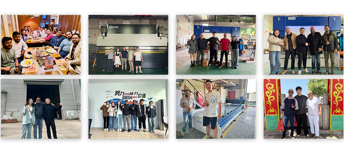
Customer photos
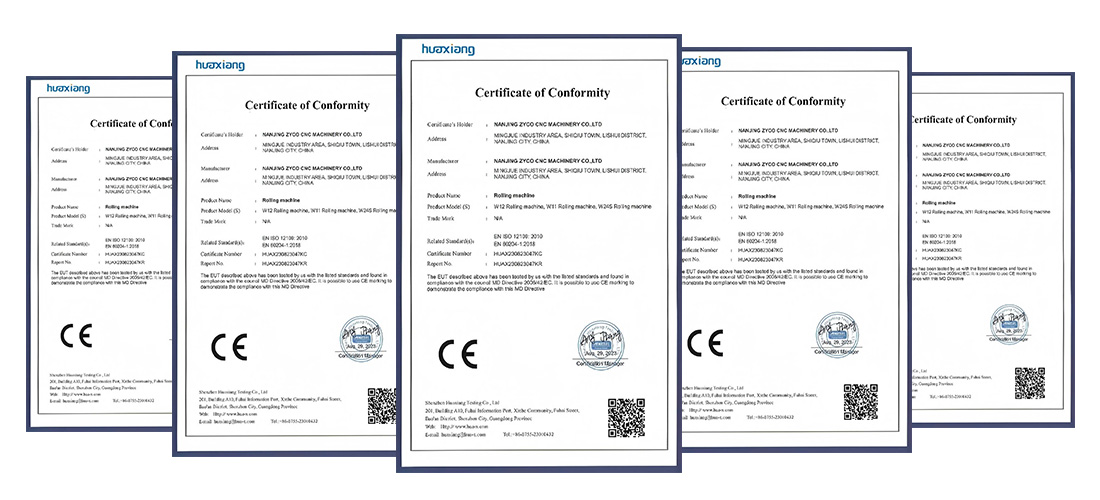
Certificate of Honor
Q: Can this press brake perform offset bending?
A: Yes. Offset bending can be performed when the required profile, tooling, and workpiece dimensions are within the machine's working range. The tooling arrangement should be checked for each specific application.
Q: Can this press brake bend narrow flanges?
A: Yes, narrow flanges can be produced when the workpiece geometry and tooling provide sufficient clearance. The minimum achievable flange size depends on the material thickness, die opening, and tooling configuration.
Q: Can this press brake handle heavy sheet metal workpieces?
A: Yes, provided that the workpiece weight, dimensions, and required bending force are within the machine's rated capacity. For large or heavy parts, suitable material handling equipment may also be required.
Q: Can the press brake be used with special forming tools?
A: Yes. Special punches, dies, and forming tools can be used for certain applications when their dimensions and mounting method are compatible with the machine. This allows the press brake to handle more specialized forming requirements.
Q: Can ZYCO review my part drawing before I order a press brake?
A: Yes. You can provide your part drawing and processing requirements, and our technical team can evaluate the bending process, tooling, and machine configuration. We can then recommend the most suitable solution for your products.





 RETE SUPPORTATA
 italiano
 English
 français
 Deutsch
 русский
 português
 español
 한국의
한국의 Türkçe
 العربية